
Quality Control of Digital MEMS Microphones
A digital MEMS (MicroElectroMechanical System) microphone, otherwise known as a microphone chip or silicon microphone, is a pressure-sensitive diaphragm on a PCB (Printed Circuit Board) which is sometimes be no bigger than a match head. They are used in various consumer devices as well as in automotive and industrial applications. A digital MEMS microphone combines an acoustic sensor as well as an A to D converter on one silicon chip, and is usually connected directly to a signal processor. Due to the rapidly-growing use of voice recognition applications, digital MEMS microphones are often used in an array formation. In quality-testing the microphones, the absolute specification values, and, even more important, the values of all microphones in the array relative to each other must be tested. This article explains how to interface digital MEMS microphones to an acoustic test system and how to measure the relevant key parameters for a reliable QC (Quality Control) procedure.

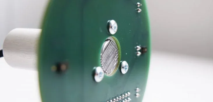
To test the acoustic parameters of a digital MEMS microphone, the digital signal must interface directly with the audio analyzer system, or be converted to a different format, e.g. analog. The typical parameters of interest for a QC test are the same as for the testing of most other microphones; Sensitivity, Frequency response, Distortion, and sometimes Signal to Noise ratio (SNR). For a complete microphone characterization typically performed in a lab environment, parameters such as EIN (Equivalent Input Noise), PSR (Power Supply Rejection), PSRR (Power Supply Rejection Rate), and Dynamic Range are measured or calculated. Optionally, the directional behavior of a microphone at different frequencies can be measured by using a turntable.
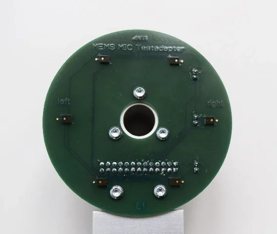
Array of 6 digital MEMS microphones
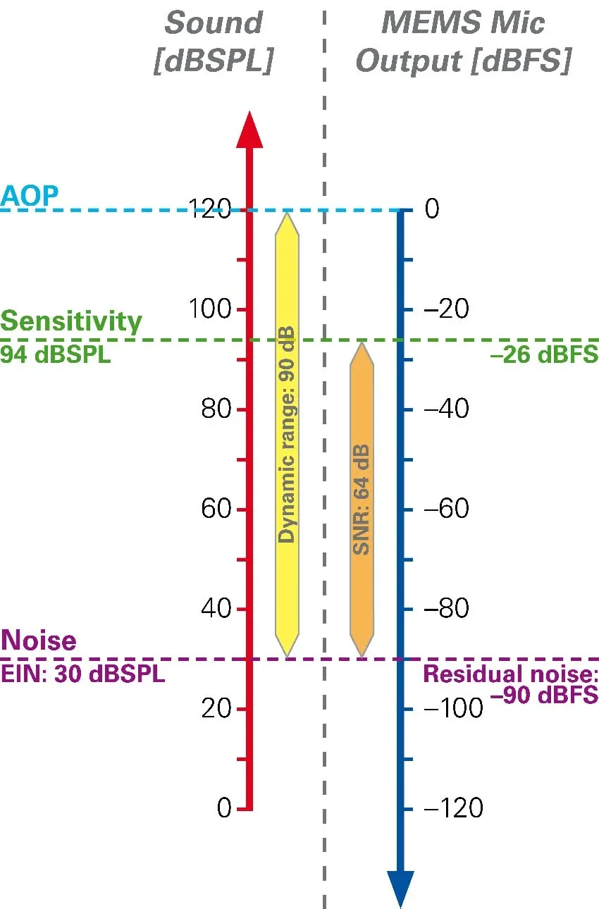
For all absolute measurements (those that are not expressed in % or dB) the units for digital MEMS microphones are different. While the sensitivity of analog microphones is expressed in mV/Pa or dBV/Pa, the unit for digital microphone is dBFs. This stands for “decibels below Fullscale” and describes the headroom of a digital microphone from 94dBSPL (1Pa) to the maximum digital output of that microphone. This point of maximum digital output is also referred to as the AOP (Acoustic Overload Point).
Testing single MEMS microphones is very rare. In most cases, the MEMS microphones are tested on an assembled PCB containing several MEMS microphones. For characterizing the performance of that PCB, it is of interest how the assembled MEMS microphones behave relative to each other. A typical parameter is the “Sensitivity Span”; the difference between the highest and lowest sensitivity measured on the assembled MEMS microphones.
Acoustic vs. Digital vs. Analog Domain
Digital MEMS microphone peculiarities
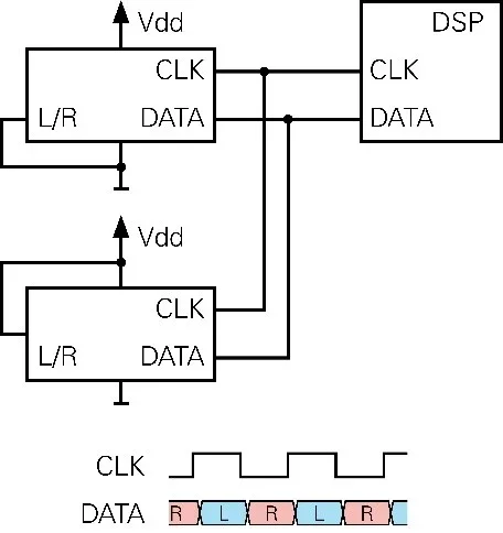
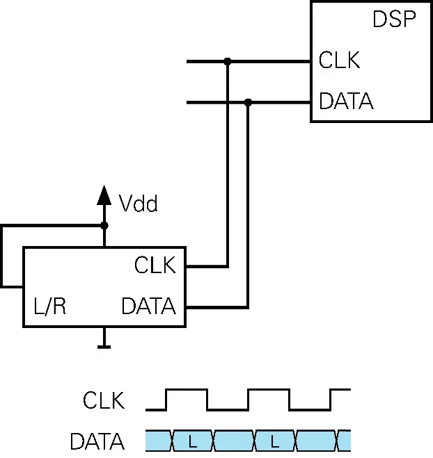
Digital MEMS microphones deliver data in the ½ cycle PDM format. The microphone requires a CLK input, and delivers its data on a DATA output. Furthermore, two microphones share one data line. Therefore, each microphone is configured to be either a “left” or “right” microphone. This is done by hardwiring the L/R input pin to either Vdd or ground. MEMS microphones are supplied mostly by 1.8V or 3.3V.
In normal operation, the “left” microphone writes a data bit on each rising edge of the clock signal, while the “right” microphone writes a data bit on each falling edge. While one microphone is writing data, the other one puts its DATA output into a high-impedance mode. On the DSP that is receiving the data, the left and right signal data are then separated and put together into two signal streams.
But what happens when one of the two microphones is not assembled correctly or is missing?
In this example, the right microphone is missing, therefore only the left microphone is writing to the data line. At the falling edges, the left microphone puts its DATA line to high-impedance state. Therefore, the DATA line keeps its state as it was previously written by the left microphone. As a result, from the receiving DSP perspective, the right microphone seems to deliver the exact same data as the left microphone. The two data streams are identical! This problem must be addressed by the test system, as detecting a missing microphone is a fundamental feature when testing a MEMS array PCB.
The clock frequencies used to operate digital MEMS microphones range typically between a few hundred kHz, up to 3MHz. A lower clock rate means lower power consumption, but also lower audio quality.
To ensure digital signal integrity, it’s recommended to keep the distances between digital MEMS microphones and the audio test system as short as possible. These microphones are simply not designed to drive a long high-capacitance cable.
Normal operation of two digital MEMS microphones
Operation with one inoperative or missing MEMS microphone
A typical test system architecture
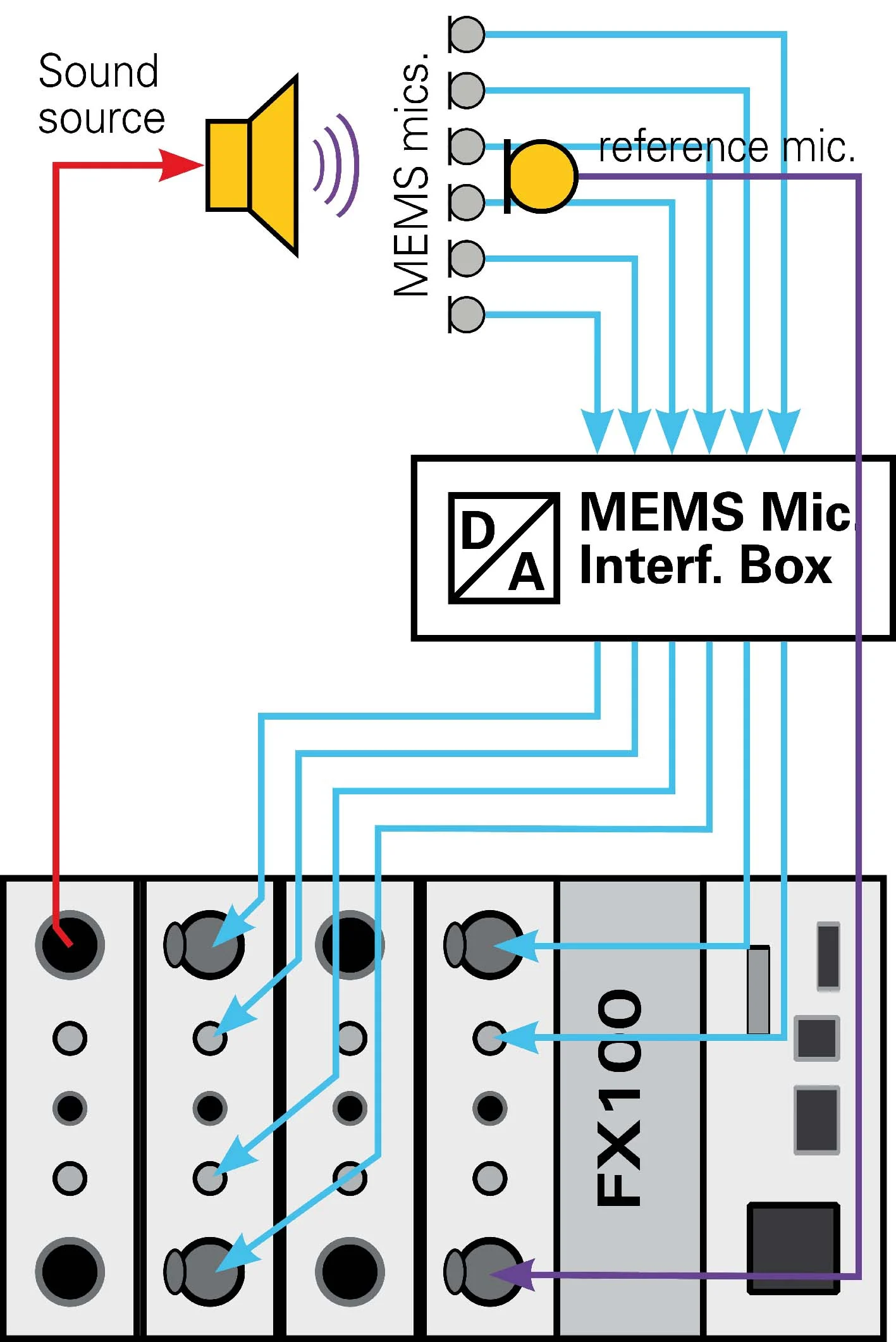
Test setup for measuring a 6 MEMS mic array PCB
The basic measurement system for testing digital MEMS mic arrays consists of an audio analyzer, a MEMS interface device a reference loudspeaker and a reference microphone. A PC software typically controls such a system.
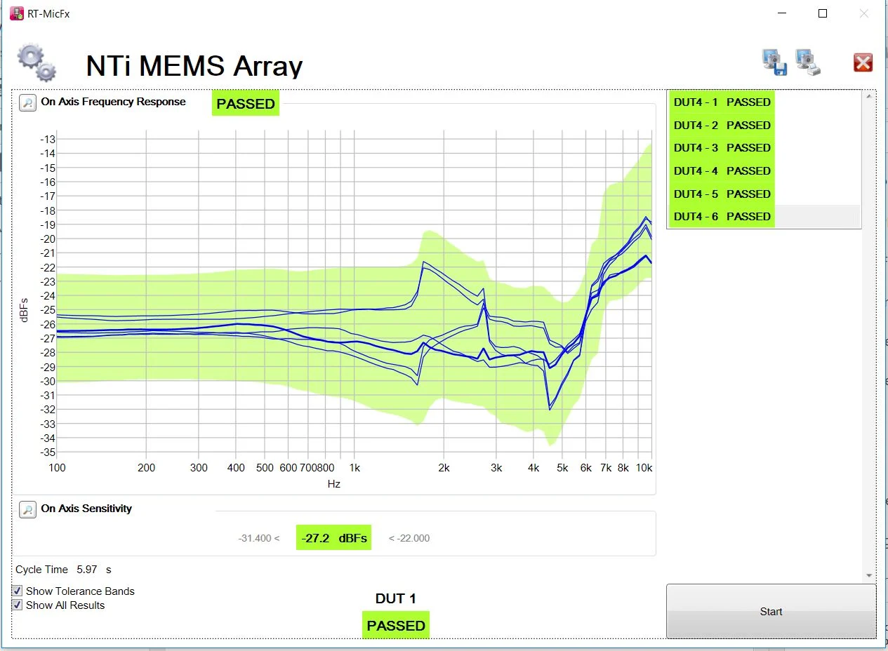
EOL MEMS Mic Array QC software